

 Deutsch
Professional, secure, private LoRaWAN
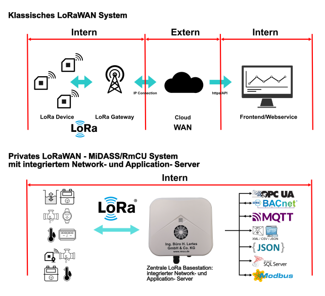
The LoRa base station is designed as an extension of the existing MiDASS/RmCU concept, enabling the connection of utility meters and smart city sensors with a LoRaWAN interface to higher-level portals such as energy management systems. Our LoRa base stations and LoRa gateways can be used to set up self-sufficient LoRa networks that do not require an Internet cloud server. LoRaWAN devices of Class A (sensors such as water meters) and Class C (actuators such as switches) are supported. For large projects, a connection via an MS-SQL database, developed and distributed by Ingsoft in Nürnberg, is also available.
Structure
The LoRa gateways integrate seamlessly into the existing MiDASS/RmCU V 4.0 concept and also enable the expansion of existing RmCU/MiDASS installations into a large LoRa network. Multiple LoRa gateways can be connected via a central LoRa base station, which includes the network and application server, to collect data across a wide area. Thanks to the integrated network and application server, you avoid the cloud connection typically required by other providers and the associated costs for sensor management and measurement decoding. This ensures your data remains GDPR-compliant and confidential within your own IP network. The system also supports bidirectional communication, allowing commands to be sent to the LoRa devices.
Classic LoRaWAN system:
Single LoRa-Basestation
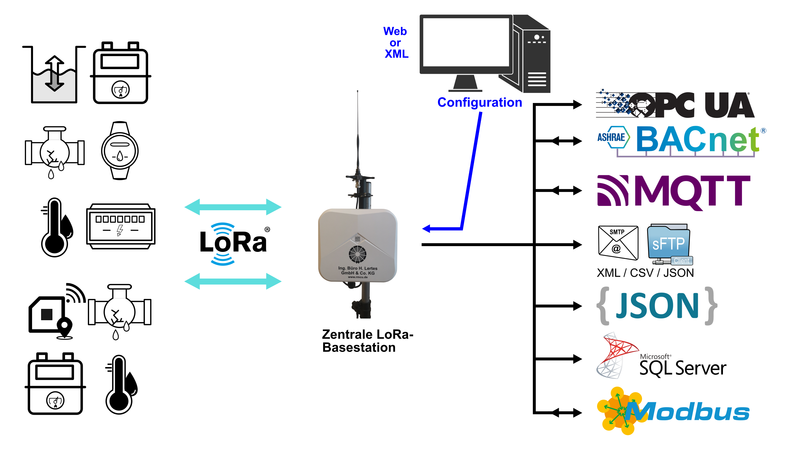
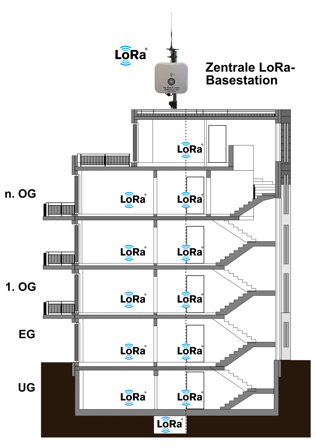
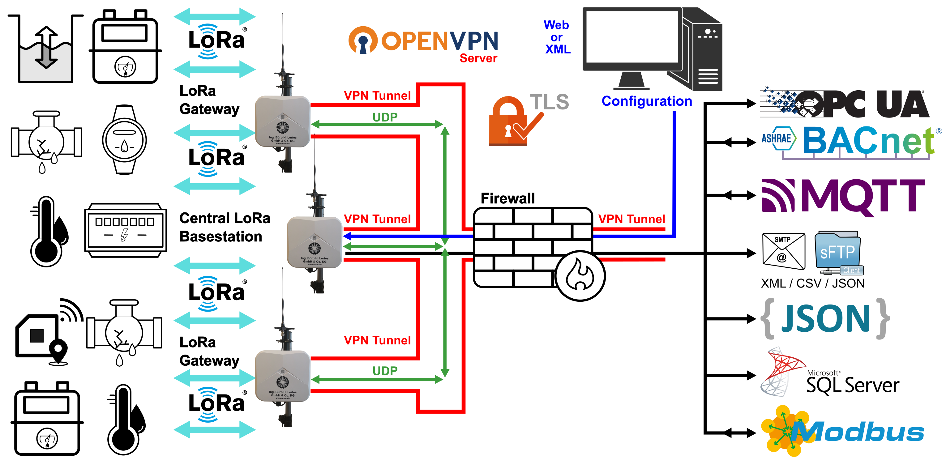
The single LoRa base station consists of a central LoRa base station with an integrated LoRaWAN network and application server and is suitable for data acquisition in larger buildings or smaller industrial complexes.
A central LoRa base station receives and processes energy data from all sensors and meters within the building, making it available for further processing via various interfaces. The following diagram shows an example of a single LoRa base station setup in the sub-meter range.
Small / Medium / Large LoRa-Network
Small LoRa-Network
(Central LoRa-Basestation + LoRa-Gateways)
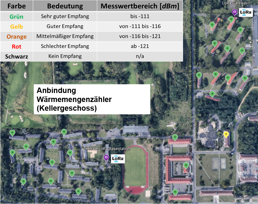
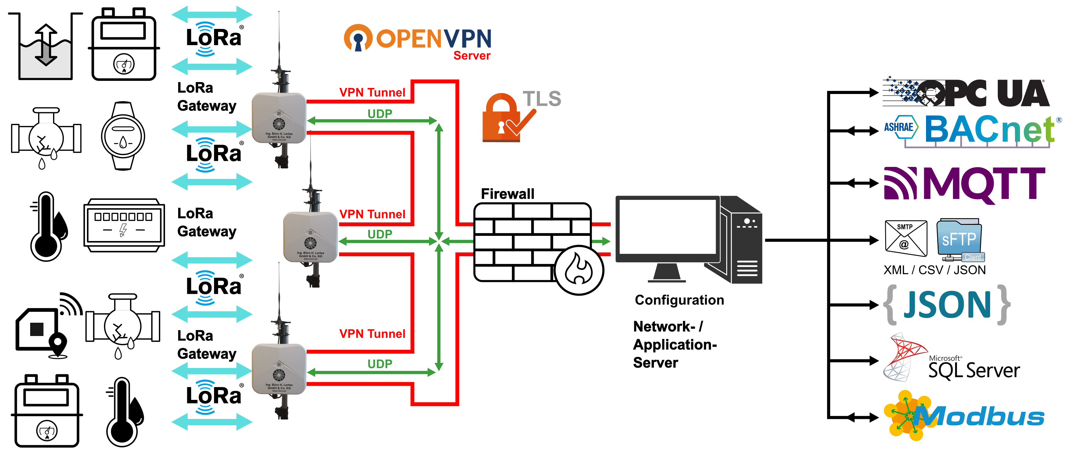
A small LoRa network consists of a central LoRa base station and a small number of LoRa gateways. The LoRa gateways, which act as additional receivers, enable larger areas, such as terraced housing estates or industrial facilities, to be equipped with a comprehensive LoRa network. Communication with the sensors is bidirectional across all stations. The LoRa gateways are connected to the central LoRa base station via LAN or LTE modem. In accordance with BSI basic protection, the IP connection can be encrypted via OpenVPN TLS.
The following figure shows an example of a LoRa network setup for monitoring a local heating network. The heat meters are located in the basement, approximately 1 m below ground level.
Medium sized LoRa-Network
(RmCU as Network- and Application-Server in the data center + LoRa-Gateways)
A medium-sized LoRa network covering a larger area consists of a network and application server and several LoRa gateways. In accordance with the GDPR and ISO 27001, the network and application server can be operated in your data center on a specially adapted RmCU, allowing several hundred sensors or consumption meters to be managed.
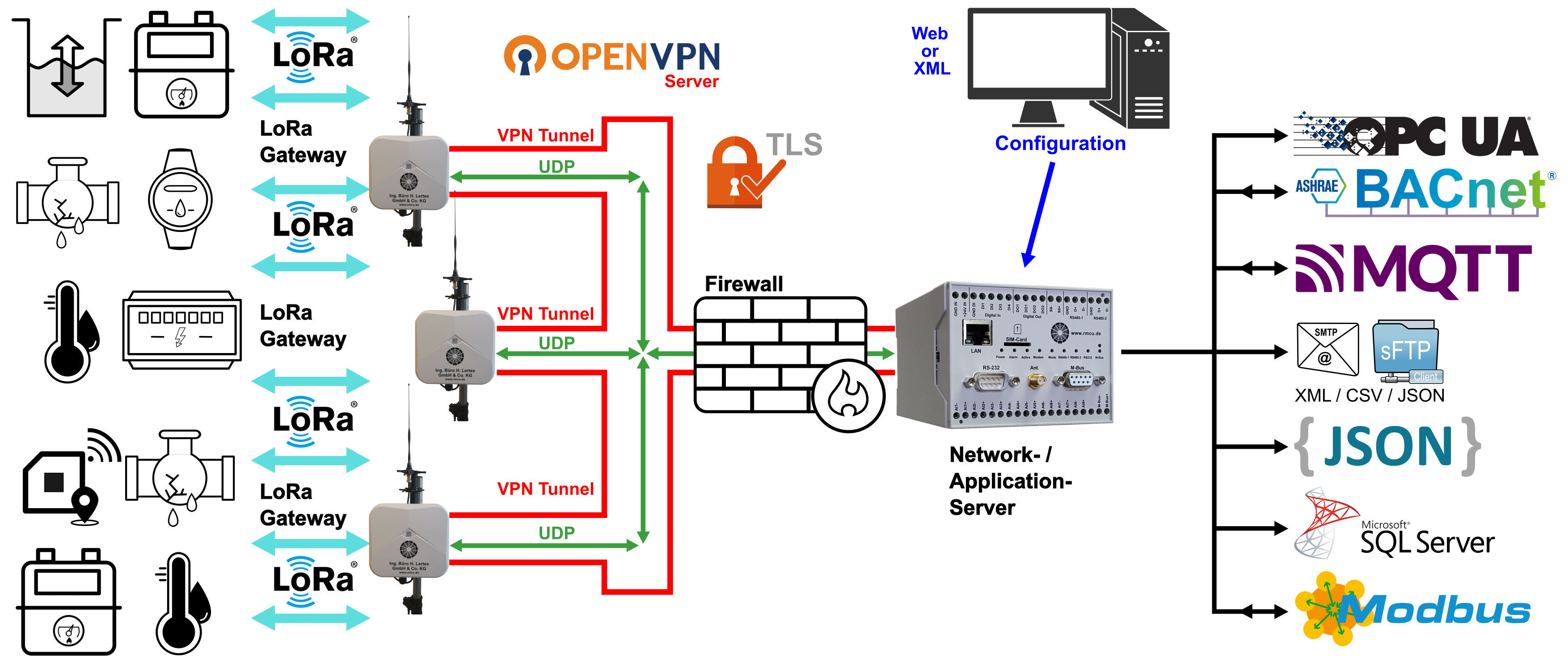
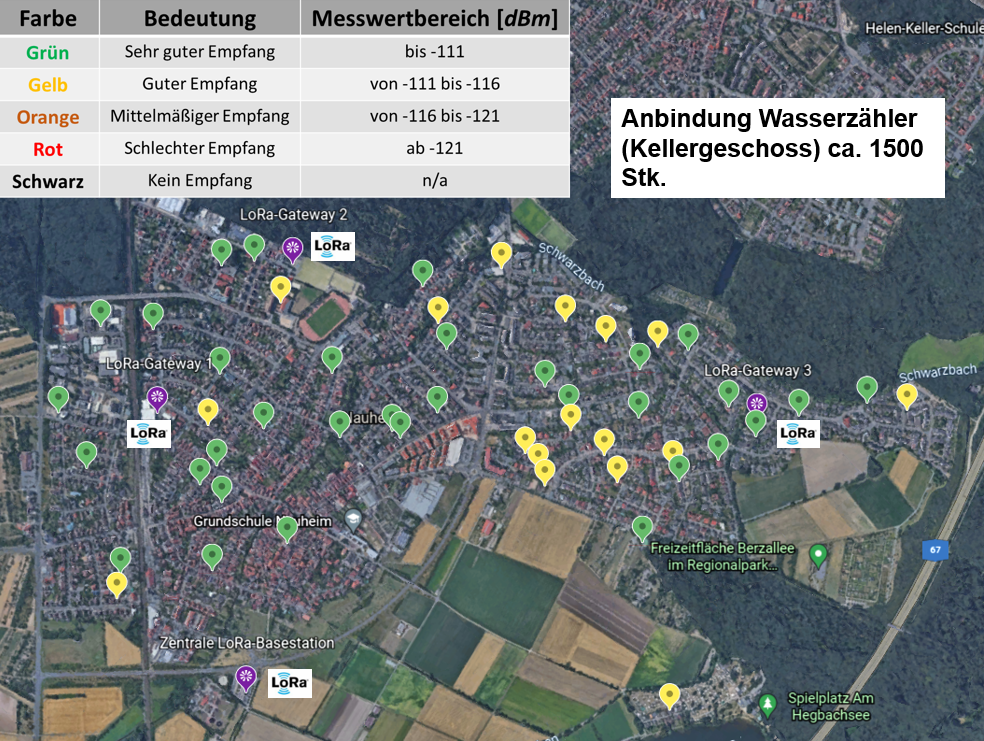
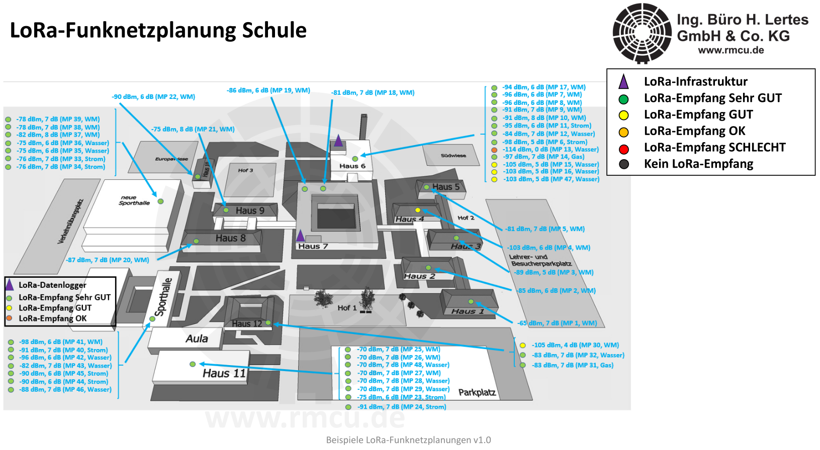
The following figure shows an example of a medium-sized LoRa network setup and the results of the corresponding random radio measurements we carried out. In this case, the focus is on connecting 1,500 water meters in the basement.
Large LoRa-Network
(Virtual machine or Linux computer as network and application server in the data center + LoRa gateways)
For large LoRa networks connecting several thousand sensors or consumption meters, the network and application server in your data center can also be operated on a Linux computer.
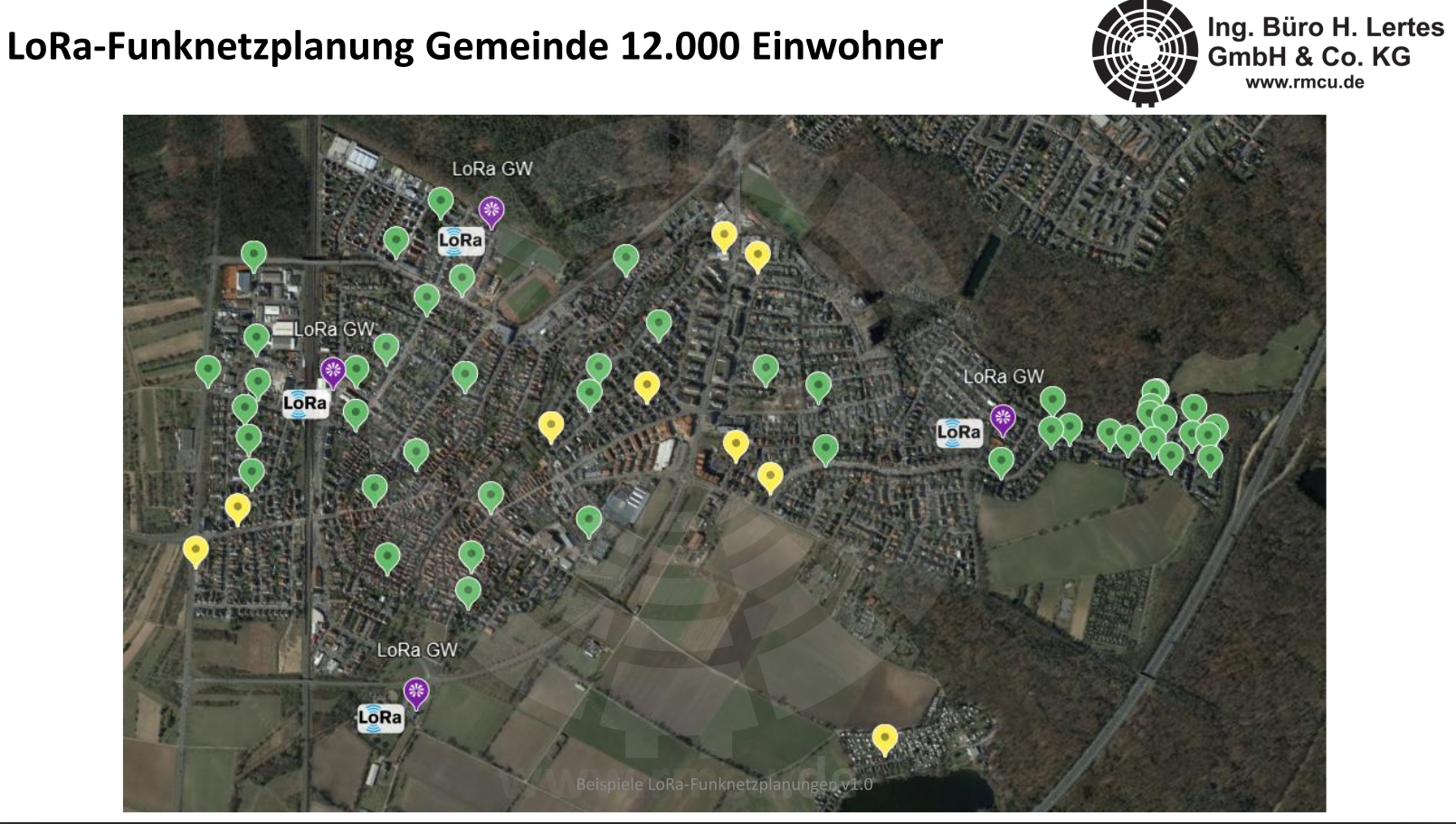
The following figure shows an example of a large LoRa network setup. It shows a large number of LoRa gateways that are connected via a central network and application server on a virtual machine and collect data from several thousand sensors or consumption meters. Alternatively, the system can also be installed on a Linux computer in a data center.

More examples from our more than 500 LoRa projects

You can find more examples from our projects here: LoRa Project Examples
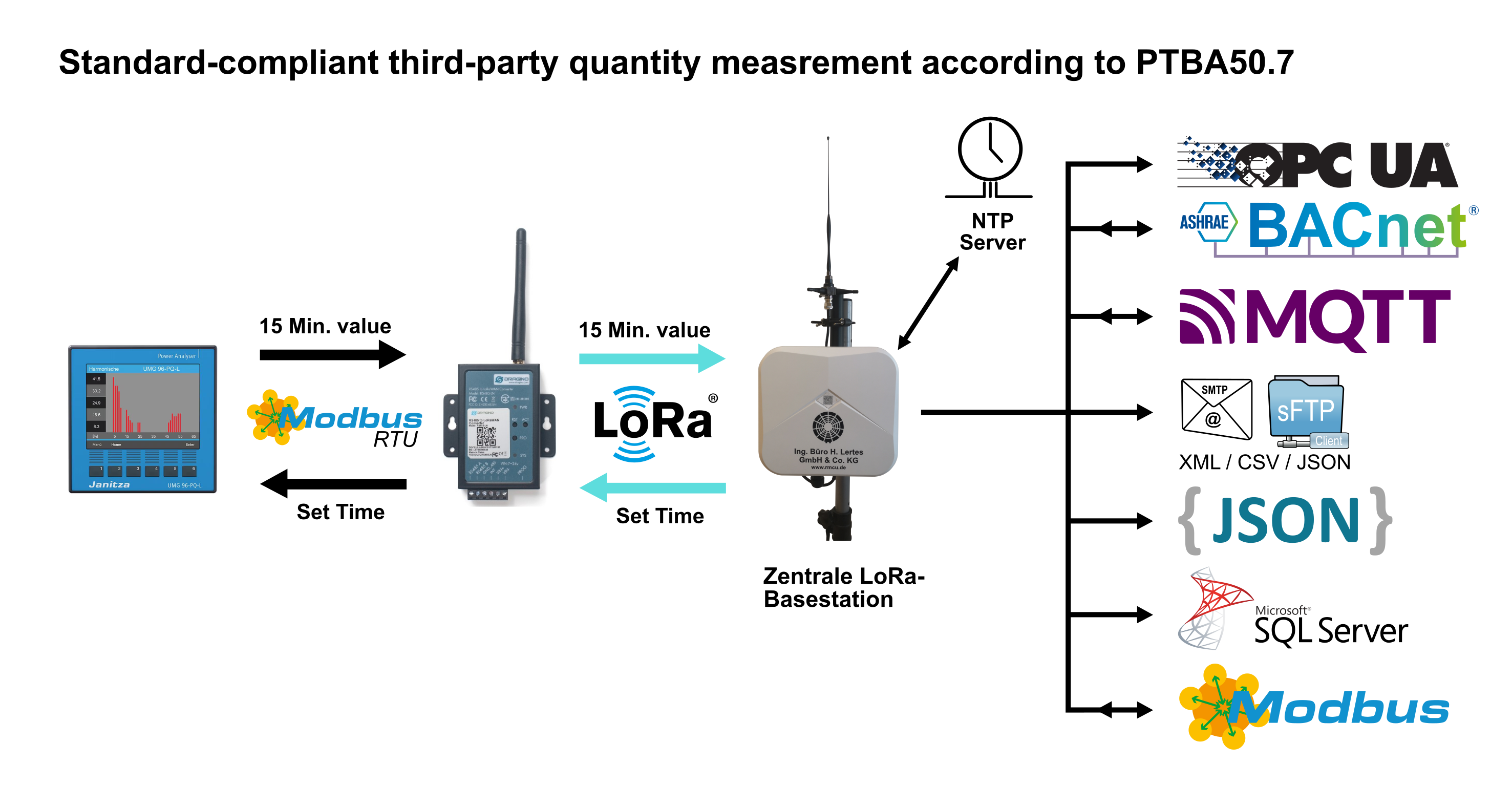
third-party measurement
Our system delivers precise 15-minute values in accordance with PTB A 50.7 and automatically performs the legally required time synchronization of the consumption meters.
- Permissible measuring instruments
- Janitza UMG 96-PA MID with local data storage via Modbus RTU
Network connection
The IP connection to the higher-level system and the UDP-based communication between the LoRa gateways and the central LoRa base station are established via LAN or an integrated LTE modem. A 450 MHz and a 5G version of the modem are available. Optionally, the central LoRa base station and the LoRa gateways can be connected via an OpenVPN server with TLS encryption (TLS V1.3). This ensures that communication over mobile networks or the internet is secured in accordance with the BSI IT baseline protection standards.

Network + Application Server
Integrated LoRaWAN network server
The management of the LoRa sensors, including the necessary keys, is done manually via the integrated web interface (German/English) or automatically via an XML or JSON interface. All quality parameters recorded by the LoRa radio system are logged and displayed.
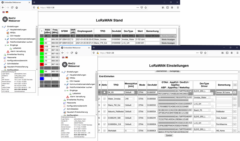
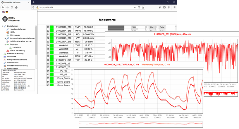
Integrated Application-Server
Depending on the sensor type, the recorded measurements can be mapped to data points. Current and historical measurements are displayed in the measurement table integrated into the web interface (German/English).
The following interfaces are available for connecting to higher-level systems:

LoRa Basestation Features
- LoRaWAN receiver with 868 MHz, 8 Channels
- LoRaWAN Network Server
- Supports LoraWAN Class A and Class C sensors
- Activation Modes
- ABP (Activation By Personalization) Mode (DevAddr / NwkSKey / AppSKey)
- OTAA (Over-The-Air Activation) Mode (AppEUI / DevEUI / AppKey)
- Decryption of the uplink messages from the end nodes, parsing of the payload.